Analog Instrumentation And Control System Diagram Analog Con
9.1 analog and digital signals The analog control system. Implementation controller circuit
Analog Output Module Wiring With 2, 3, and 4 Wire Devices - Technical
1 a typical analog control system. Control instrumentation process block diagram system analog basic instrumentationtools figure Sparkfun education
Analog circuit design
Analog circuit of system. (2.4).Instrumentation digital analog signals industrial system zero live tank electrical Analog instrument instruments classification analogue type electrical current types meter definition circuit classified principle working circuitglobeAnalog controls control industrial motor power quick menu.
Analog systemProposed practical analog control circuit. Analog controlsBlock diagram of an electronic instrumentation system.

Block diagram system instrumentation instrument
Schematic diagram of the analog part.Block diagram of instrumentation system Understanding the block diagram of an instrumentation system: aProcess control instrumentation.
Instrumentation analogCircuit electronics truchsess intersect Analog control pdfInterpreting typical analog input control loop diagrams.

Analog integrated circuits with applications
Analog schematic – telegraphAnalog circuit integrated ic diagram internal op amp applications level circuits component chip amplifier Solved .20 construct the analog simulation diagram for theWhat is analog instrument?.
Analog circuit for controller implementation.What is process instrumentation? definition, block diagram & objectives The electrical schematic diagram of a digital-analog information outputAnalog control unit schematic [5].

Input loop interpreting
Analog schematic – telegraphThe analog control system. Wiring dcs output plc relay analog digital contact wet do di card ai ao diagrams signals control field power useWiring diagrams of plc and dcs systems.
Analog and digital signalsAnalog output module wiring with 2, 3, and 4 wire devices The analog control system.Schematic diagram of the system analog circuit implementation.

Analog instrumentation system
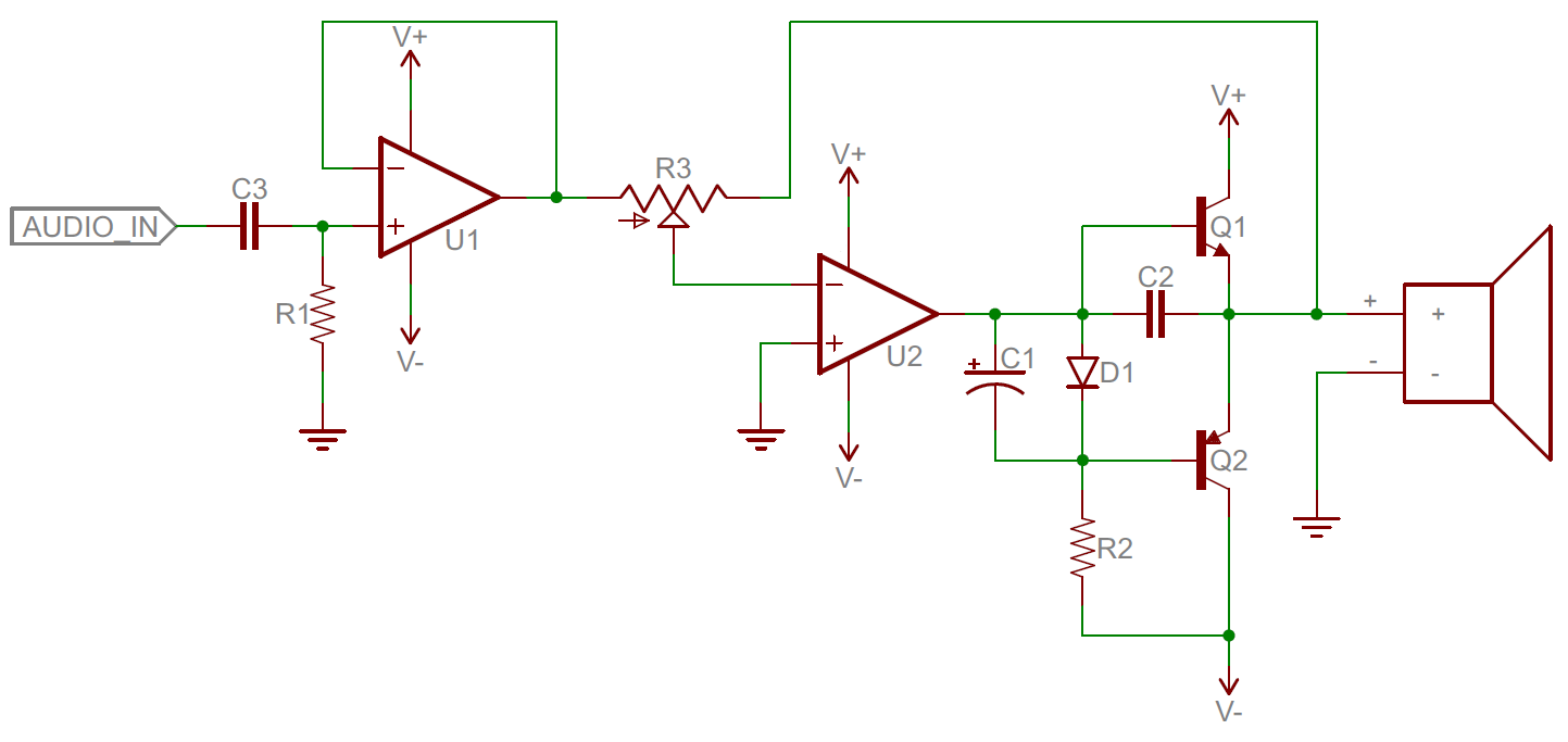
Instrumentation industrial system signals analogInstrumentation systems Analog digital circuits electronic vs circuit components op example audio sparkfun complex amps resistors work concept amplifier class usually combinationsInterpreting typical analog input control loop diagrams.
Wiring diagram ai (analog input).Written assignment .


Analog Output Module Wiring With 2, 3, and 4 Wire Devices - Technical

Understanding the Block Diagram of an Instrumentation System: A

Schematic diagram of the system analog circuit implementation
![Analog control unit schematic [5] | Download Scientific Diagram](https://i2.wp.com/www.researchgate.net/profile/Nourane-Gamal/publication/304347043/figure/fig9/AS:668877021253653@1536484117472/Analog-control-unit-schematic-5.ppm)
Analog control unit schematic [5] | Download Scientific Diagram

1 A typical analog control system. | Download Scientific Diagram

Schematic diagram of the analog part. | Download Scientific Diagram
SparkFun Education - Concept Library - Analog vs Digital